Last Updated: 4/04/04
I use the circuit above to monitor the voltage level of my Li-Poly battery packs during flight. The two Super Bright LEDs light up when the voltage level of the pack gets below 10 volts. I currently use Li-Poly cell packs that have three cells in series and four or five cells in parallel (3S4P or 3S5P). With this configuration the nominal voltage level of the packs is 11.1 VDC. With Li-Poly batteries it is very important not to discharge the cells below a certain voltage level. This level is usually between 2.5 and 3 VDC per cell. With three cells in series the minimum voltage level the pack should reach is around 9 VDC. I chose the 10 volt threshold level to give me some extra time to land the helicopter before the 9 VDC minimum volt level is reached.
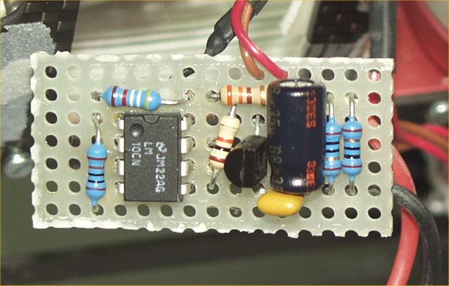
Here's how the circuit works; The heart of the voltage monitor is a National LM10CN analog IC. This IC has a voltage reference and one op-amp in a 8 pin DIP package. The op-amp is used as a voltage comparator that compares the voltage level of the voltage reference and the battery pack that powers the monitor circuit. When the battery voltage, through the voltage divider R3 and R4, goes below the reference voltage, the op-amp turns on transistor Q1. This lights up the LEDs by allowing current to flow through the devices.
Since the voltage reference on the IC is 200 millivolts, you need to reduce the battery voltage to that level when the battery reaches 10 VDC. Resistors R3 and R4 act as a voltage divider and set the threshold level of the monitor circuit.
Resistor R6 set the maximum current level through the LEDs. You may need to change this resistor depending on how many LEDs you have, their current requirements and the voltage range of the battery pack. The maximum current through an LED is usually 20 to 50 milliamps.
Resistors R1 and R2 and capacitors C1 and C2 act as a power supply filter. The resistors will also act as a fuse in case something where to short on the board.
All resistors are 1/4 watt. Resistors R3 and R4 should be 1 % metal film components. All of the other resistors can be 5%. The value of C1 is not critical and C2 is probably not needed. C1 can be in the range of 10UF to 100UF. The value of R5 is also not very critical. Anything between 4.7K and 22K should be fine.
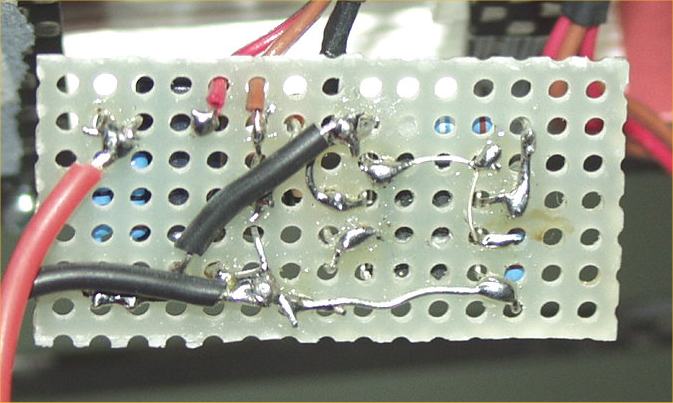
I constructed the circuit on a small piece of fiberglass breadboard material. The two photos below show the top and bottom of the monitor board.
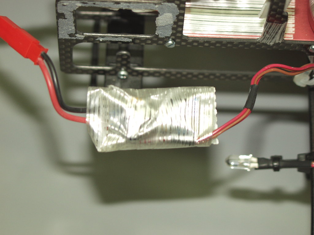
I used some shipping tape to protect the board. I would have used shrink wrap tubing but I didn't have any in-stock that would fit over the board.
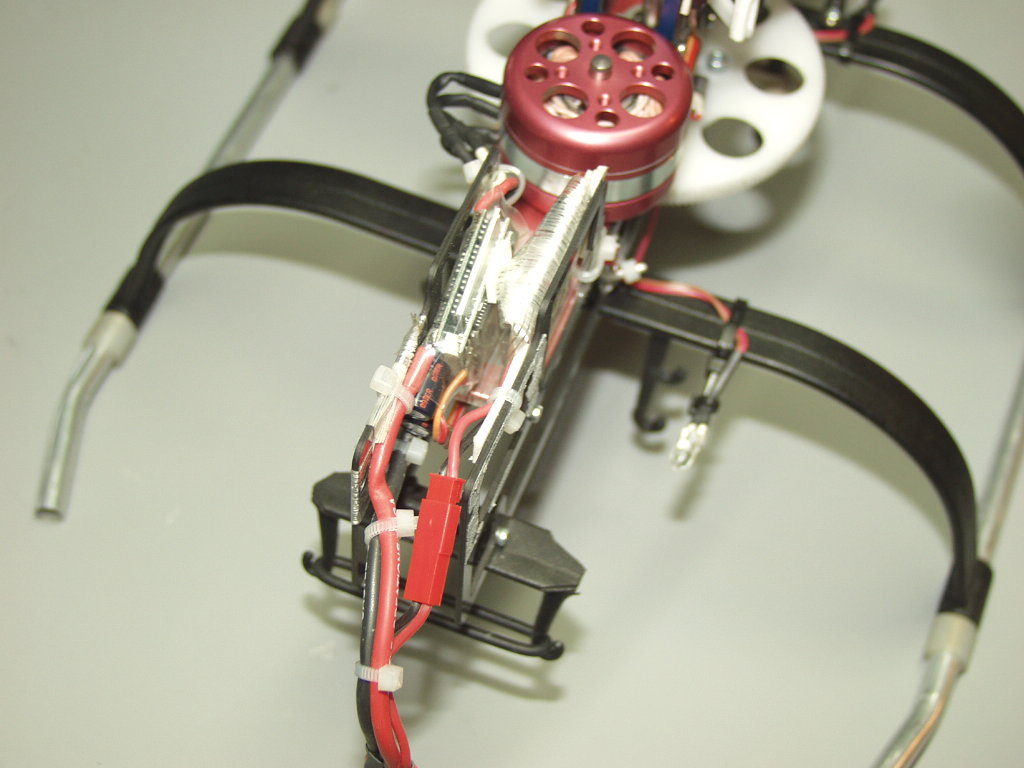
I then placed the board in the helicopter. I used some double sided foam tape to secure the board to the frame. The photo below shows the monitor board next to the Castle Creation's Phoenix 45 ESC (Electronic Speed Controller) brushless motor controller.
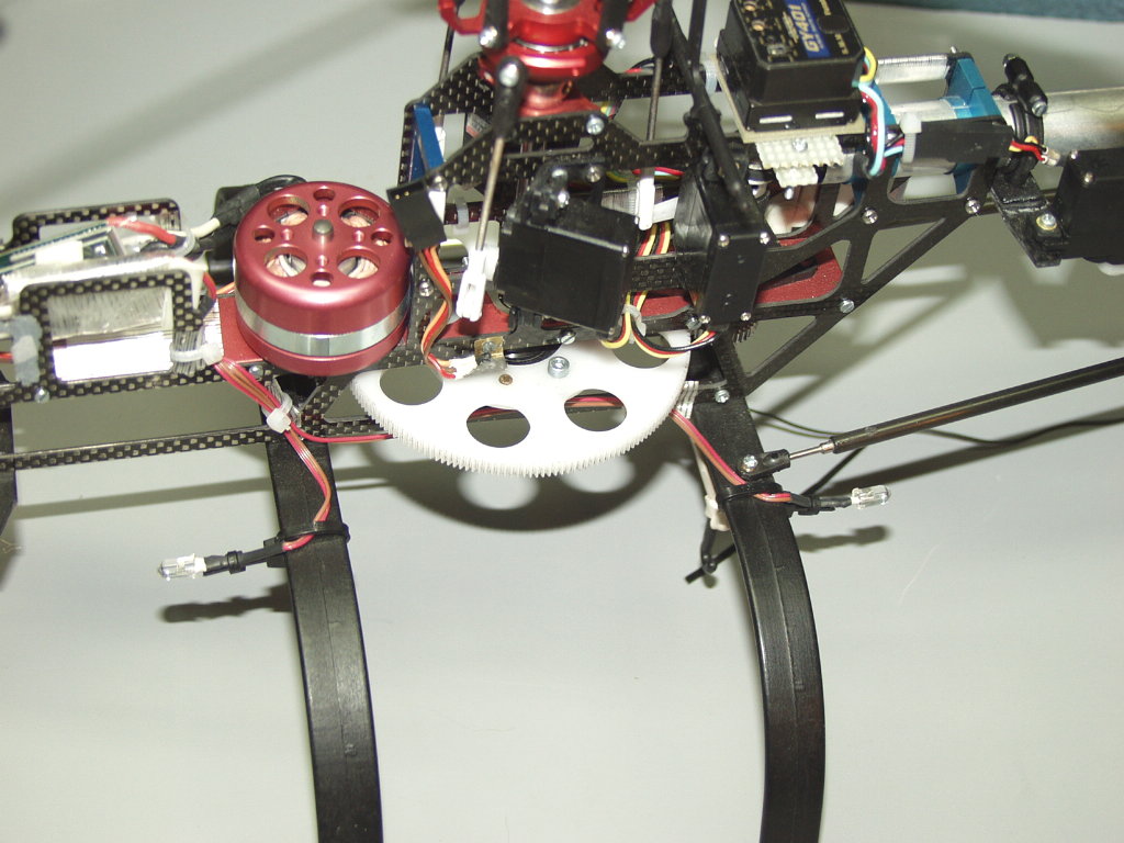
And the next photo shows the location of the LEDs mounted to the landing gear.
This page viewed
times since April 2, 2004
[ Home ] [ Top ] [ ECO 8 Home ]