Lasted Update: 1/29/05
New - TP6000 4P3S Battery Test
The plots below show the RPM drop over time using my In-Flight Datalogger. The two drops in RPM are when I landed and let the RPM drop using the throttle stick of my Eclipse 7 transmitter. I did this to produce some known points in time.
The plot below expands the top part of the plot above.
Download: First Flight Data
Second and Third Flights and Battery Packs
The plots below show the difference between three TP8000 battery packs. The orange line in the plots below were created using my first TP8000 pack and the green line my second. My first pack has around 50 charge/discharge cycles and the second and third around 20. I tend not to use the second pack since it weighs 72 more grams and tends to get unbalances after a few flights. I'm not sure why the second pack I purchased was different then my first and third pack? The second pack had a balancing circuit included in the battery pack. I removed the circuit since I manually monitor and rebalance the cells myself when needed. I believe the difference between RPM on packs #1 and #3 is do to #1 having more charge/discharge cycles. I think pack #2, while having about the same number of charge/discharge cycles, has a lower average RPM do to the extra weight.
Download: Second Flight Data and Third Flight Data
Here's some detail information on my setup; I used my ECO 8 #1 helicopter to produce the date above. The Phoenix 60 Electronic Speed Controller is programmed to operate in the High RPM Governor mode, Electronic Timing Advance was set to Standard and the PWM Switching Rate was set to 11Khz. To charge my battery packs I use a Schulze 6-330 or Triton charger. For the test flights above I used the 6-330 charger. I note this because this charger charges Li-Poly batteries to a little higher terminal voltage then the Triton charger. This difference yields about one or two minutes of extra flight time.
To operate my ECO8s I use a HI-Tech Eclipse 7 Transmitter. This transmitter has two knobs that control the collect pitch and motor RPM. For the flights that created the data above the RPM knob was set to ~80% and the collective knob ~40%.
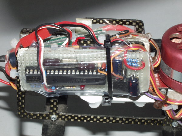
The photo below shows the datalogger I built to record the the RPM during a flight. I am using a PIC18F252 Microcontroller and a 24C1024 Serial EEPROM to save the data. To measure the RPM the Microcontroller was programmed to count the pulses from the RPM sensors (see below) and convert the data to RPM. Each sample is then saved to the 131K byte EEPROM during the flight. The sample time can be programmed for a sample rate of 1 to 255 seconds. The plots above use a sample time of 5 seconds. With a sample time of 5 seconds the accuracy is ~12 RPM. The breadboard datalogger weighs about 25 grams and the RPM sensor another gram or two.
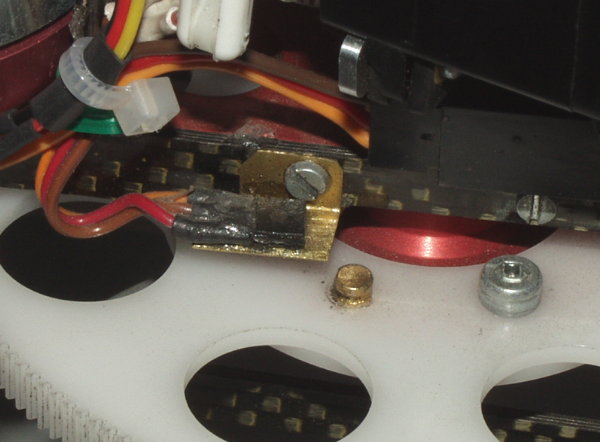
To measure the RPM on my ECO8s I use a Allegro MicroSystems UGN3503U Hall-Effect sensor and some small magnets from Wondermagnet.com. The Hall-Effect sensor produces a change in output voltage when a magnet is near the sensor. The photo below shows the sensor and two of the four magnets I use on the main gear. I use two per side so that I get a larger signal from the sensor and I place another set of magnets on the other side to balance the main gear. I'm not sure that the other set is necessary. Since I have two sets I get two pulse out of the sensor per revolution.
Update 12/22/04: I have now added two more channels to my In-Flight datalogger. One measure the battery terminal voltage and the other battery discharge current. I also made some changes to how the datalogger calculates RPM and the sample rate used to record the data. The information above used a sample time of 5 seconds. I am now using a 2 second sample time and the RPM accuracy is now one or two RPM.
The plots below show the RPM verses battery voltage, current and power (Power = Volts * Current) during my first flight with the current sensor installed. You can click on any of the plots below to see a larger image.
Download: Flight Data
During my 22 minute 30 second flight the calculated current discharge was 5550 MAH (Milliamp Hour). When I charged the battery pack using my Schulze 6-330 it put in 5575 MAH back into the pack. At the time of this flight the helicopter weighed 1605 grams.
Here are some statistics for the flight.
Maximum RPM = 1752, Average = 1578
Maximum Battery Voltage = 12.6, Average = 10.9
Maximum Current = 18.7 amps, Average Current = 14.8 amps
Maximum Power = 203.9 watts, Average Power = 162.7 watts
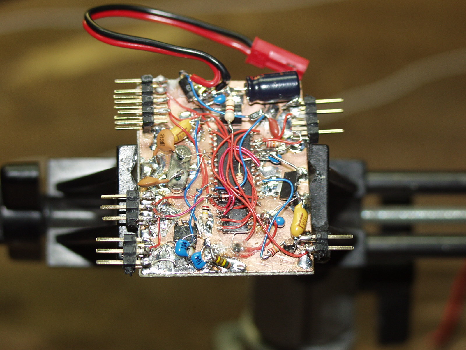
Update 1/12/05 - This photo shows my next generation of In-Flight datalogger. This version uses some surface mounted devices to reduce the size and weight. It's not very pretty but it seems to be working very well.
Now that I have a tool to monitor the performance of my ECO 8, and have a few flights of data with the my current configuration, I made my first change to my ECO 8 setup. I changed the motor pinion for 19T to 20T. The plot above shows the headspeed RPM and battery voltage difference before and after I made the change.
Based on the data I recorded, the average headspeed increased by ~60 RPM. Theoretically the headspeed should have increased 84 RPM, but do to the extra current needed to drive the motor, the battery voltage decreased resulting in a lower RPM. The current increased was about 1 ampere or ~10 watts of power.
Update: 1/29/05 - I purchased a Thunder Power TP6000 4S3P battery to see if the extra voltage to the ESC/motor would reduce the RPM drop over time. The plot above shows the headspeed, battery voltage and current using the new battery and a 16 tooth motor pinion. As you can see it didn't help. There is still a drop of about 150 RPM (~ 8 %) during a 18 minute flight. I used this pinion calculator to come up with a 16T pinion. It calculated the headspeed would be 1786 RPM using a H8 motor and 4 Li-Poly batteries. The average RPM during the flight was 1725, so the calculator did a pretty good job at calculating what the headspeed would be.
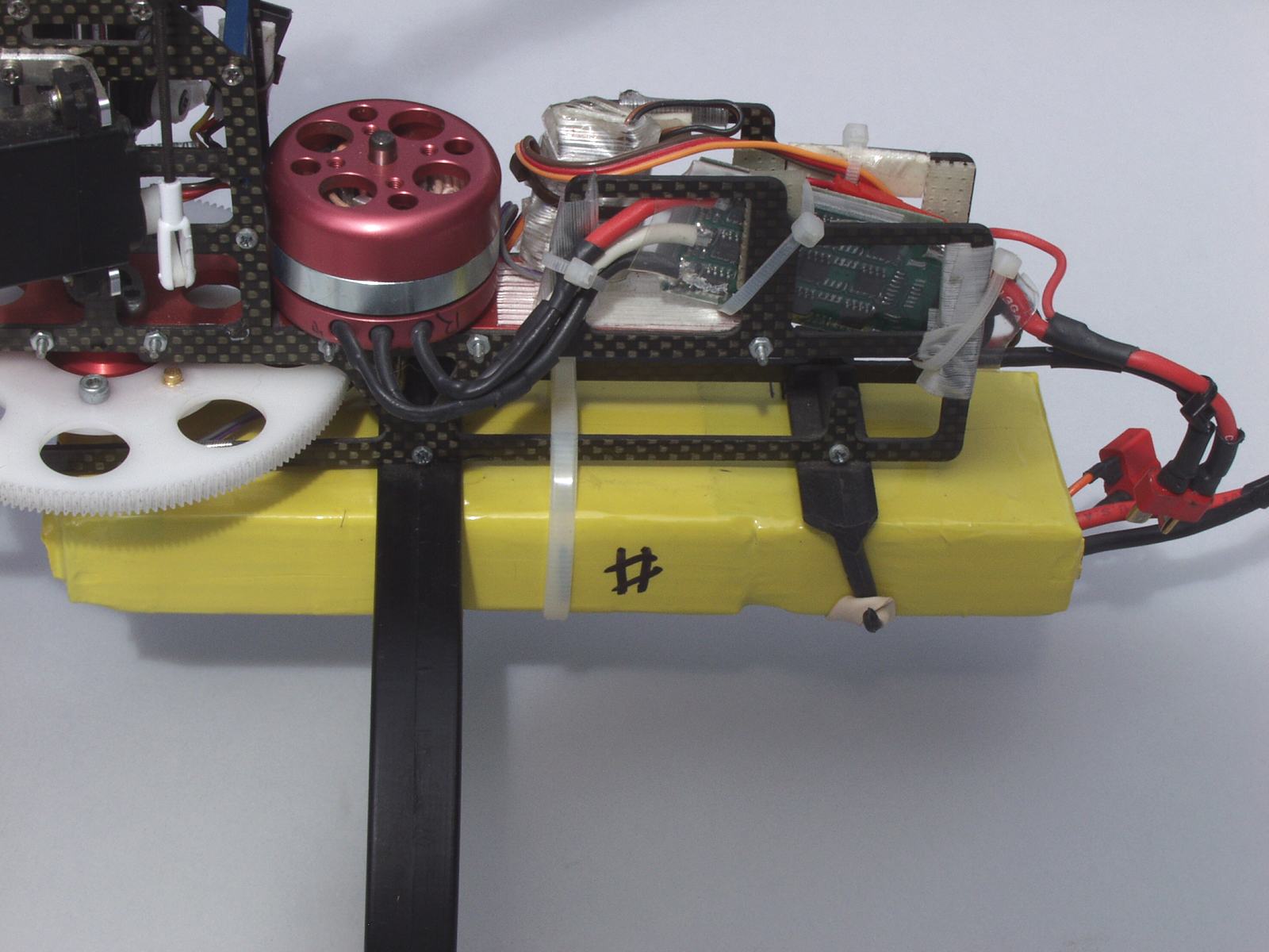
I would have liked to use a smaller pinion since I don't need this high of a headspeed for the type of flying I am doing. Do to a clearness problem with the CF frame and upright support I can't get a smaller pinion to mate with the main gear. To get the 16T pinion to fit I needed to file down both the frame and upright support. This photo show how near the motor is to the frame using a larger pinion.
Here are some statistics for the flight after the first minute of data:
Maximum RPM = 1802, Average = 1718
Maximum Battery Voltage = 14.7, Average = 14.2
Maximum Current = 17.4 amps, Average Current = 14.9 amps
Maximum Power = 251 watts, Average Power = 211 watts
Discharge MAH = 3966
This page viewed times since December 4, 2004
[ Home ]