Last Updated: 08/29/2016
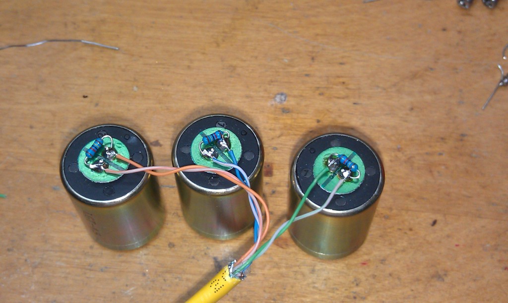
This photo shows the three sensor elements with damping resistors. The cable used is shielded CAT 5 or CAT 6 Ethernet wire with 4 pairs. One pair is not used.
The solid colored wire from each pair is soldered to the senor nearest the Polarity Post as shown above.
The three sensor elements are then placed in the case. Make sure you have the vertical element pointing downward.
Some hot-glue is used to secure the sensor elements to the case.
The PC board with rubber gasket.
Completed sensor with DB15 Connector.