The clock has two parts to it. One is the main LCD display and an "antenna" that is about 5 inches long. The two are separated with ~3 feet (1m) of wire. I bought the unit some time in early December 1997, and when I first got it, I could not get it to lock up to the time signal. I tried everywhere in my house, nothing. So I set it up in a high place in my house hoping that it would lock some day. I kept checking every day, again nothing. After about a week of this I was getting pretty discouraged. Then one day, just before Xmas, it locked up. It turns out that the people at NIST, who send out the WWVB signal, increased the power of their transmitter from a whopping 10KW to around 20KW (they will be increasing it to 40KW in a few months) on DEC. 19th 1997. This increase was enough for the clock to lock to the signal. At this point I had something to work with. No need to poke around if I can get it to lock....
So I opened the main unit, like any good electronics nerd will do, to see what I could find. I was expecting to find something that looked like a small radio receiver in it. I didn't see anything that looked like one. I then started probing around with an o-scope to see what I could find. All I could find was some LCD drive signals, nothing that could be easily converted to a time reference for SDR. I then look at the signals around the wire from the antenna assembly. There where 4 wires that terminated on the PC board. They are marked VE+, GND, DCF and PON. With the scope I found that +VE had the + battery voltage (two AAA batteries power the unit for a voltage of around 3 volts) on it. The GND was the - battery side. The PON would be at +3 volts when the unit was not trying to lock to WWVB, and ground if it was using the receiver. And the DCF signal had some sort of "digital" signal on it when PON was at GND. The unit tries to lock onto WWVB every 3 or 4 hours. If it can lock onto the signal, or times out in 5 to 10 minutes it sets the PON signal back to +3v.
I then open the "antenna" assembly. It turns out that it has the antenna and a complete receiver in it. The assembly has an ~5 inch ferrite rod, and a coil wound on it, and a small PC board with a potted IC. Since I didn't know what the format of WWVB was, I did know that it was transmitted at the low freq. of 60khz (not mhz), I did an Internet search and found that it has a one bit per second data rate (see http://www.boulder.nist.gov/timefreq/ for more info on WWV and WWVB). To send the time code the transmitter reduces its power by 10db for 200 milliseconds to signal a binary 0, 500ms for a binary 1 and 800ms for a framing mark. The framing mark is sent every 10 seconds. After locating the antenna/receiver in a good location, the unit is pretty sensitive to the orientation and location, I could see the 1 pps data bits on the DCF wire with the scope when the receiver was on. You can force the unit to try and lock on the time signal by turning the unit off and on again.
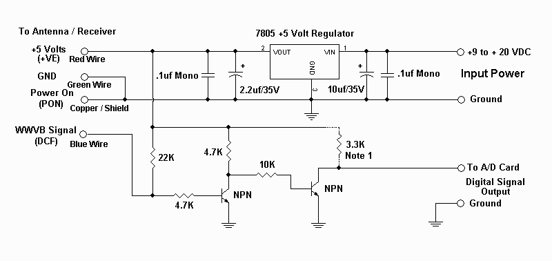
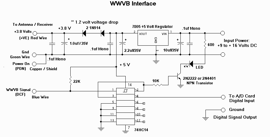
Since the receiver was located in the antenna assembly, and the main unit turns the receiver on and off, I decided to remove the receiver from the main LCD unit and power it my self. I also came up with a simple circuit that would take the DCF output and drive a digital input port on my A/D card or the PC-Labs 711s card. Below is the schematic I came up with. Rather then power the unit at 3 volts (I didn't have a 3 volt regulator on hand) I tried using +5 volts. It seems to work fine despite the extra 2 volts.
I then modified SDR to read the signal from the receiver. Since I already had code that recognized a 800ms top of the minute pulse from WWV, I was able to change the code so it could use the 800 ms framing pulses from WWVB. WWVB sends out two back to back framing pulses, one second before the top of the minute, and another one at the top of the minute. SDR uses the two framing pulse to know when the top of the minute happens and uses this mark to keep the system time accurate. It doesn't seem to work as well as my WWV setup put it was able to keep one of my SDR systems accurate to within +-15ms. I can get better accuracy, +- 5 ms, with my $200+ short-wave receiver tuned to WWV on 5.0 MHZ, and outside antenna, but for $40.00, and a handful of parts, +-15 ms is not to bad.
If you would like to try the receiver clock with SDR the first thing to do is get one from Radio Shack and see if you can get it to lock in your location. If you can't get it to lock hopefully you can bring it back. If you can get it to lock then build up the interface circuit (or contact me and I can build one for you) and connect it to the digital input port 0 of my A/D card (pin 32 and one of the digital GND pins) or port 0 of the PC-Labs card. You will also need to contact me for a new version of SDR.

