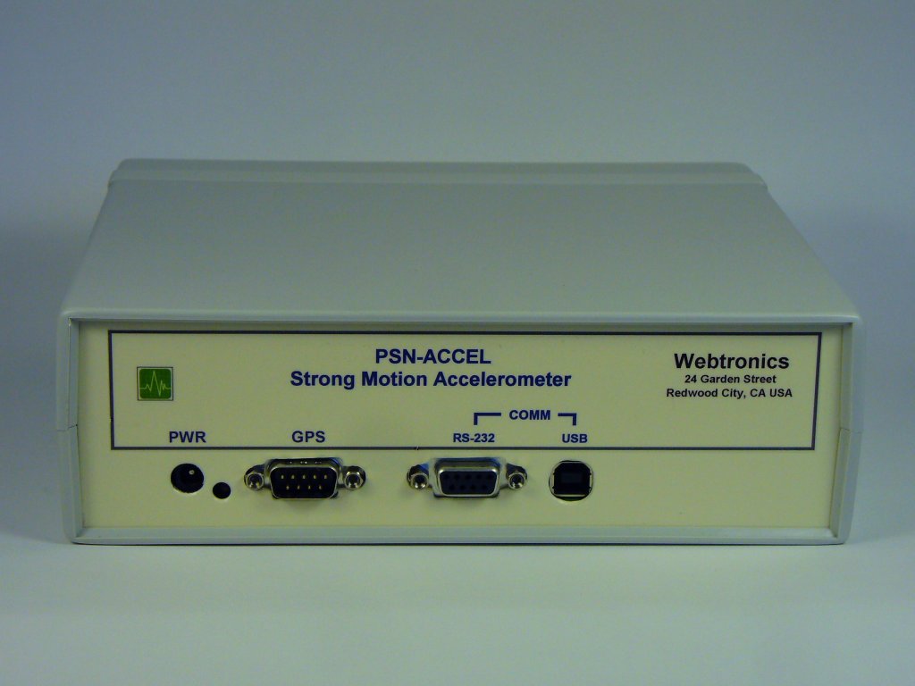
PSN-ACCEL 4-Channel Strong Motion Accelerometer Sensor Board
Last Updated: 06/11/2017
Note: This board is no longer in
production
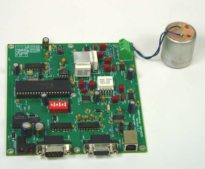
PSN-ACCEL Board with Optional 4.5Hz Geophone Connected to the Auxiliary Channel
Block Diagram
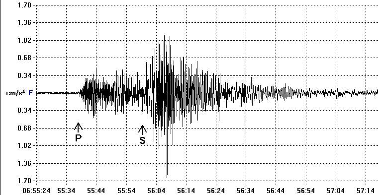
Magnitude 5.3 event 180km (112 miles) from the PSN-ACCEL sensor.
Description:
The PSN-ACCEL 4-Channel 24-Bit Triaxial Accelerometer sensor board is based on
a piezoresistive silicon accelerometer chip manufactured by Measurement
Specialties, Inc. The specifications on the sensor chip can be viewed here.
The board also includes an auxiliary 24-Bit channel that can be used with a
weak motion sensor like a 4.5Hz or 1Hz geophone. Each channel is digitized
using a 24-Bit Delta-Sigma Analog to Digital Converter (Note 1) manufactured
by Cirrus Logic. The datasheet for the Cirrus Logic CS5532 ADC chip can be viewed here.
Supported sample rate are: 15, 25, 30, 50, 60, 100, 120 and 200SPS.
The PSN-ACCEL board supports both USB and RS-232 Comm Port
interfaces. A GPS receiver can be connected to the board for
accurate time stamping of the ADC data.
Applications:
- Earthquake Detection and Location
- Seismic Studies
- Aftershock Studies
- Structural Testing
- Vibration Monitoring
Features:
-
Acceleration range: +-2g
- Low Noise: < 100 ug rms
- Dynamic Range: ~100dB
- Frequency Range: DC to 50 Hz at 200 SPS
- Wide Input Power Range: 7 to 28VDC
- Low Power Operation: < 1 watt with Garmin GPS18x Receiver
- DC Response: Can be used to measure Tilt and Angle
- ADC Programmable Gain Range: 1, 2, 4, 8, 16, 32 and 64
- Non-linearity: +-.5% [typical]
- Temperature Performance: ±1.0% [typical]
- RS-232 or USB Interface
- Auxiliary Channel: Input for Geophone or other weak / strong motion sensor
Specifications:
- Analog Inputs: 4, 3 strong motion and 1 auxiliary channel
- Resolution: 20 Bits at 100 Samples Per Second
- A/D Converter Chip: Cirrus Logic CS5532
- Convert Type: 24-Bit Delta-Sigma
- Sample Rates: 15, 25, 30, 50, 60, 100, 120 and 200SPS
- GPS Support: Garmin GPS 18x LVC or Sure Electronic MG1613S
- Timing Accuracy with GPS Receiver: < 2 Milliseconds
- Board Size: 5.5 x 5.0 inches or 13.97 x 12.7 cm
Cost:
No longer in production.
Sensitivity:
The overall sensitivity to acceleration for each channel is
controlled by Programmable
Gain Instrument Amplifier (PGIA) on the ADC chip and the number of bits
used from the ADC converter. As the sample rate increases the number of useful
ADC bits decreases. Below are some suggestions for the number of bits
to use and PGIA gain value :
- Sample Rate - 100, 120, or 200 SPS: Bits = 20 or 21, Gain = 32
- Sample Rate - 50 or 60 SPS: Bits = 21 or 22, Gain = 32
- Sample Rate - Below 50 SPS: Bits 22 or 23, Gain = 32 or 64
These settings should be added to WinSDR in the Channel Settings
dialog box. Earthworm users will need to add these settings to the PsnAdSend.d
file. See http://www.seismicnet.com/PsnAdSend76_ovr.html
and http://www.seismicnet.com/PsnAdSend76_cmd.html
for more information.
Calibration:
Each sensor chip has a serial number and is calibrated by the manufacturer.
A calibration datasheet will be supplied for each axis. This datasheet
contains information on the sensitivity of the sensor chip expressed in
millivolts / g, with a typical chip producing about 7 to 8 mV / g. The calibration
datasheet looks like this. Infield calibration
is also possible by using the earth's 1 g force and rotating each axis 180 degrees.
Power Requirements:
The PSN-ACCEL sensor board can operate on a wide input voltage
range. The minimum input voltage is ~7.5VDC and the maximum ~28VDC. A diode on
the board is used to prevent damage to the board if the input power is reversed.
The table below list the power requirements in milliamps with and without the
Garmin GPS 18x receiver connected to the sensor board.
| Input Voltage |
No GPS |
W/GPS |
| 7.50VDC |
100ma |
130ma |
| 12.0VDC |
60ma |
80ma |
| 15.0VDC |
50ma |
68ma |
| 24.0VDC |
36ma |
46ma |
Software:
WinSDR (Download)
can be used to record data using the PSN-ACCEL sensor board. This
program is included with the purchase of the board. WinSDR will run on
Windows XP, VISTA and Win7. Both 32-Bit and 64-Bit version of the program are available.
This Windows DLL Driver and Linux Library can be used by programmers who
would like to write their own datalogger program or add the sensor board to an
existing program. The DLL Driver
zip file or Linux Library
includes an example, written in VC++ 8.0, showing how to use the
PSNADBoard.DLL file.
Earthworm, a powerful seismic software package
that can run under various operating systems, can receive data using the PSN-ACCEL board or WinSDR.
See this link for more information.
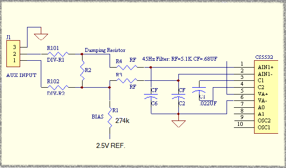
This channel has a differential input with a input voltage range of +-2.5V
or 5V Peak-to-peak when the Programmable
Gain Instrument Amplifier gain set to 1. With the gain set to 64, the
maximum PGIA gain, the input voltage range is +- 39 millivolts. A differential
voltage divider can be placed on the board to allow for larger input voltage
swings. See schematic below. R2 can be used as a damping resistor for the
sensor or used as one leg of the voltage divider.
The user should use shielded 2 conductor wire when connecting a senor like
a Geophone to the input. The + output of the sensor should connect to J1 screw
terminal 2 and the - output to terminal 1. The shielded part of the wire
should be connected to terminal 3. At the other end of the wire the shield can
be left open or connected to the metal case of the sensor. Before connecting
the shield to the case of the sensor the should check with a Digital Volt
Meter to make sure there is no resistance between the case and one of the
output coil terminals. If the sensor is going to set right next to the
PSN-ACCEL board the user can use a short run of twisted pair wire without the
shield. Just leave the ground screw terminal 3 disconnected and only connect
terminals 1 and 2 to the sensor's output coil.
If the user is going to drive the input with something other then a
coil the put terminals must be biased at +2.5V and swing up to 5V and down to
ground. Since the input is differential one terminal needs to be going +V
while the other -V.
Auxiliary Channel Input Schematic
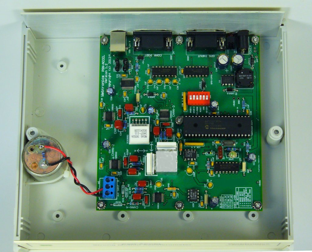
Input/Output Connector Information:
Auxiliary Input J1:
This connector is a three terminal screw block. See the above
for more information. While looking at the top of the board with J1 to your
left the connector pinout is as follows:
- Left-Hand screw terminal = -IN
- Center screw terminal = +IN
- Right-Hand screw terminal = Ground
Power Supply Connector J2:
The power connector on the board is a standard 2.1mm X 5.5mm male jack. Positive
voltage must be applied to the center pin. A diode on the board will
prevent damage if the power is reversed. The DC input range is 7.5 volts to
28 volts. See power requirements above for more
information.
GPS Comm Connector J3:
This connector is a 9 pin, DB-9 male connector used to communicate to a
GPS receiver. A straight through serial cable should be used between the A/D
board and the GPS's receiver interface board. See this page for a GPS
timing system compatible with the PSN-ACCEL board. The connector has the
following pinout:
- Pin 1 - CD (Carrier Detect) Input, Used for the 1 PPS signal from the
GPS receiver
- Pin 2 - Receiver Data Input from the GPS Receiver
- Pin 3 - Transmit Data Output to the GPS Receiver
- Pin 4 - +5 VDC for Garmin GPS 16/18 Power
- Pin 5 - Ground
- Pin 7 - Ground for Garmin GPS 16
- Pins 6, 8 and 9 - Not Connected
Comm Connector J4:
This connector is a 9 pin DB-9 female connector used to communicate to
the PC running WinSDR. A straight through serial cable should be used
between the A/D board and the your computer. The connector has the following
pinout:
- Pin 1 - Not Connected
- Pin 2 - Transmit Data Output
- Pin 3 - Receive Data Input
- Pin 4 - DTR (Data Terminal Ready) Input - CPU Reset Line
- Pin 5 - Ground
- Pin 6 - Not Connected
- Pin 7 - Not Connected
- Pin 8 - Not Connected
- Pin 9 - Not Connected
The DTR line ( Pin 4 ) is used to reset the CPU on the A/D board. This
line should be below 2 VDC for normal operation. If the LED on the board
does not come on, it may be do to this line holding the CPU in the reset
state. Position 1 of Switch SW1 can be used to disable this feature. If
disabled, off position, the host computer can not reset the CPU on the A/D
board.
USB Interface J5:
This USB Type B connector is used to communicate with the PC. The USB
interface chip used on the A/D board is a FTDI
FT232RL. Windows or Linux drivers (32-Bit or 64-Bit) can be downloaded from here.
Notes:
- Usable ADC bits dependent on sample rate and on-chip Programmable Gain Instrument Amplifier (PGIA) gain setting.
- We get the 4.5Hz geophone elements on the used market, so this item may not always be available.
This page viewed  times since
October 10, 2012
times since
October 10, 2012
[ Top ][ Equipment ]
[ Home ] [ How to Order ]
Contact Information