Below is some information on how to build a low cost (< $25.00USD) USB GPS receiver that includes a 1 PPS (Pulse Per Second) signal. NTP (Network Time Protocol) servers need to use a 1PPS pulse from the GPS receive for accurate system timing using a local GPS receiver. Just using the serial NMEA messages alone is not enough information for accurate time-keeping. I recently found a cheap receiver module on eBay that breaks out the 1PPS signal to a solder pad along with the normal serial input/output and power lines. Most cheap receivers on eBay have a on-board 1PPS signal that drives the status LED, but there is no solder pad to break out the signal. You can solder a wire to the receiver module to access the 1PPS signal but this requires good soldering skills.
The other thing that caught my eye about this receiver is it is advertised to be "Low Power" at 25 milliamps. In reality its closer to 35-40ma. The difference may be that the power draw specification does not include the on-board antenna, just the U-BLOX UBX-G7020-KT chip itself.
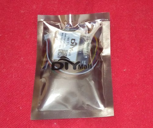
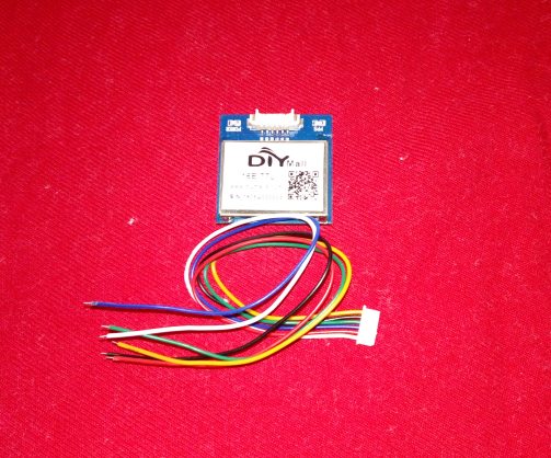
The receiver I found is sold by DIYMall. You should be able to find several sellers on eBay or Amazon.com that sell them by searching for the following 'G28U7FTTL Replace VK16E GMOUSE GPS Module'. The cost on eBay is around $9.00USD with free shipping from China. I recently purchase 2 receivers from China from the eBay seller flyfun_diymall. I ordered it on May 7th and received it 11 days later. Below are photos for the receiver.


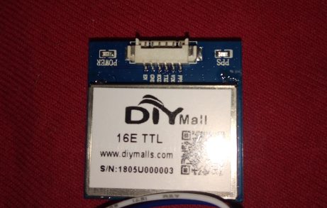
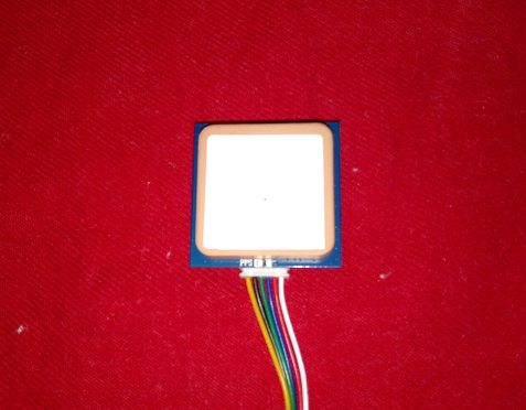
Unlike other GPS modules this one uses a 6-pin connector. The mating connector and wires are included with the receiver.
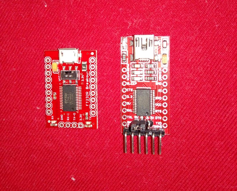
The receiver module itself does not support USB. It uses a 3.3 volt 9600 baud serial interface for communication. The 1PPS signal is a 3.3 volt positive going pulse that occurs at the top of each second. I have not measured the pulse length with an o-scope but I think it is around 100 milliseconds. Since the receiver does not support the USB interface I purchased a FTDI FT232RL breakout board from Sparkfun.com. Here's the link to their breakout board: https://www.sparkfun.com/products/12731. The cost is $15.00USD. I like Sparkfun products because they have very good documentation that includes the schematic of their products. Cheaper FT232RL breakout boards can be found on eBay or Amazon. Be careful with cheaper modules out there because they may have a counterfeit FT232RL chip in them. The photo below shows the Sparkfun module on the left and a $8.00 module that I purchased on Amazon.com on the right. I have not tried the module on the right yet but it should work the same as the Sparkfun module. One difference between the two modules is the Sparkfun module uses a micro USB connector and the other module use the larger mini USB connector.
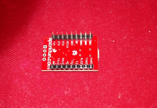
The first thing I did was solder 2 9-pin .1 inch header pins to the Sparkfun module. This is not absolutely necessary as you could hold the module down with some double sided tape and solder the GPS wires to the top of the board.
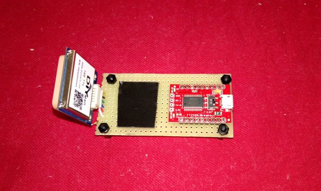
I used a small piece of fiberglass breadboard material to hold the GPS receiver and USB modules. The only complaint I have about the GPS module is there are no mounting holes. So to mount the receiver to the board I used a small piece of 3M Outdoor Mounting tape. This stuff is very strong so you may want to use some weaker tape if you plan to remove the module at a later time. I used some 5 minute epoxy around the .1 header connectors on the top of the board to hold the USB module in place.
Next I solder the GPS wires to the USB module. It's hard to see but I also used some small buss-wire on the unused input pins to connect them to +3.3v.
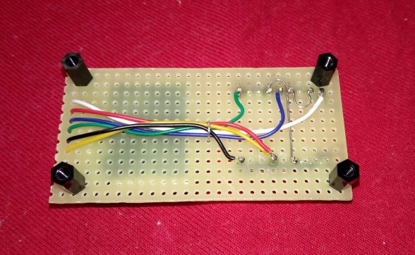
Here is the connection list:
GPS 1PPS Signal (white wire) -> USB Module DCD pin
GPS Transmit Output (blue wire) -> USB Module RXD pin
GPS Receive Input (green wire) -> USB Module TXD pin
GPS Ground (black wire) -> USB Module Ground
GPS +5 Volt Power (red wire) -> USB Module VCC pin
GPS Enable ( yellow wire) -> USB Module VCC pin
The following unused inputs on the USB module should be connected to the VCCIO pin: DSR, RI, and CTS
NOTE: The Sparkfun module has a 5V / 3.3V switch on it. This should be set to the 3.3V position. The USB module I purchased on Amazon.com uses a 3 pin jump that serves the same function. So make sure it is on the right pins.
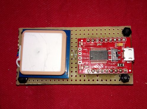
The completed USB GPS Receiver
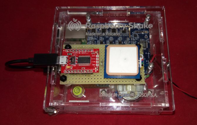
I mounted the GPS receiver to my new Raspberry PI 4D SHAKE digitizer. The RShake is used to record local earthquakes. More information about the Raspberry Shake can be found here.
I placed the RShake in my garage next to my other earthquake sensors. The brown sensor next to the RShake is a Kinemetrics FBA-23 accelerometer and the yellow sensor is a 4.5Hz 3-Component Geophone. The +5 volt power draw of the RShake 4D is around 390ma to 400ma with the GPS Receiver and 345ma to 350ma without the receiver.