My WinSDR Version 4.7.8b9 datalogger program now works with all versions of the Raspberry PI SHAKE Digitizer
Index:
The information below documents my testing of a GPS receiver with the SHAKE digitizer on a Raspberry PI single board computer. The GPS receiver is used to supply accurate time information to the NTP server running on the PI. This may be useful for people running the SHAKE software on a system without Internet access.
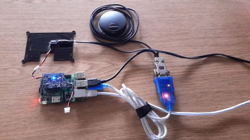
For this write-up I will be using a wireless Raspberry PI 3 and a Garmin GPS 18x LVC receiver. Other GPS receivers with a 1 pulse per second (1PPS) signal should also work. This document should also be useful to people who do not have a SHAKE digitizer but want to setup NTP with a GPS receiver on a PI board. Besides the GPS receiver and PI 2 or 3 board you will also need a RS-232 to USB converter adapter like this one. I recommend an adapter that uses the FTDI chipset. You must use one that is recognized by the Linux Kernel. FTDI based adapters can be purchased on eBay or Amazon.com for around $15.00USD. On SHAKE systems the USB adapter is needed because the one UART on the Raspberry PI is used by the SHAKE A/D board.
First we will go through the basic installation of the software on the SD Card. I like to use SanDisk Ultra 16GB, 32GB or 64GB microSDXC cards on my Raspberry PI systems. If you are a SHAKE user you should download the current image from OSOP. Non SHAKE users should download the current version of Raspbian.
I used my Windows 7 box to install the operating system onto the SD card. 7-Zip was used to extract the image file (Command: 7z e raspberryshakeSD.zip) and Win32 Disk Imager was used to install the image file onto the card. Remember to eject the SD card before unplugging it from the system.
At this point you can plug the SD card into the PI and apply power. A keyboard and monitor should be connected to the PI so you can complete the setup. Hardwiring the PI to your network using a Ethernet cable will allow you to log into the system using SSH. Using either SSH or the keyboard and monitor log into the system using myshake as the user and shakeme as the password. Once logged in the user can setup WIFI and change the default password. See the SHAKE documentation for more information.
Since all of the commands below require root access I just log into the root account using sudo su at the command prompt. If you do not want to do that add sudo before all commands. Here are some of the commands I run when setting up a Raspberry PI running Raspbian.
Update the package information database using: apt-get update
Non SHAKE users can upgrade to the current version of Raspbian using: apt-get upgrade Do not do this if you are using the OSOP SHAKE software!
Run raspi-config to expand the file system. Reboot the system using the reboot command as root. You can check the disk size and free space using the df -h command. This is what the output looks like using a 16GB SanDisk Ultra SD card.
Filesystem Size Used Avail Use% Mounted on
/dev/root 15G 1.7G 13G 12% /
devtmpfs 459M 0 459M 0% /dev
tmpfs 463M 0 463M 0% /dev/shm
tmpfs 463M 6.4M 457M 2% /run
tmpfs 5.0M 4.0K 5.0M 1% /run/lock
tmpfs 463M 0 463M 0% /sys/fs/cgroup
/dev/mmcblk0p1 63M 21M 43M 33% /boot
Timekeeping with a GPS receiver on a Raspberry PI requires receiving the serial NMEA messages and the 1 Pulse per Second (1PPS) signals. One or the other signal alone is not enough information for accurate time keeping. We will be using the RS-232 to USB adapter to get the serial information into the PI. For the 1PPS signal you can either use the DCD line (pin 1) on the USB adapter or wire the signal to one of the PI's GPIO pins. Using the USB adapter for the 1PPS signal is a lot easier since you do not need to do any wiring to the PI board. The disadvantage is the adapter introduces a delay between the receiver's 1PPS signal and when it is received by the PI. I have read that this delay is small (< 1ms) so all of my setup information and testing below was done using this method.
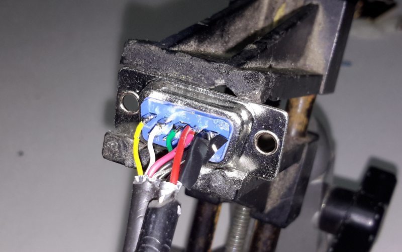
Here is the wiring needed to get the RS-232 and the 1PPS signals into the USB adapter.
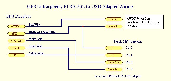
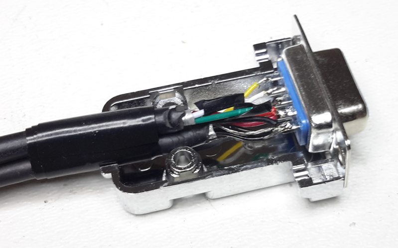
To power the Garmin GPS receiver you will need to come up with a +5VDC power source. One source of +5VDC is the Raspberry PI 40 pin header J8. Pins 2 and 4 have +5VDC on them and ground can be found on pin 6. Another source of power is an old USB cable with a USB Type A connector on it. Cut the cable and strip back the shield. Inside the shield you should find 4 wires. The red (+) and black (Gnd) wires can be used to power the GPS receiver. The two other wires, usually white and green, should be taped up so they can not short out to each other or any other wire. The connector I made for my testing looks like this.
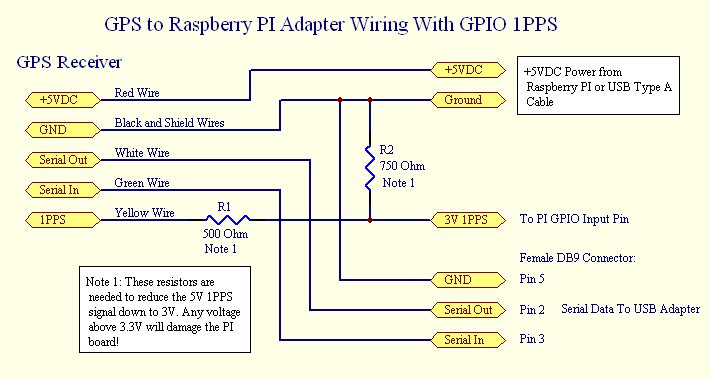
Below is the wiring diagram showing how to connect up the receiver to the USB adapter for the serial data and use one of the PI's GPIO pins for the 1PPS signal.
The two resistors R1 and R2 are used as a voltage divider to convert the +5V 1PPS signal to +3V. The Raspberry PI board is a 3.3V device and the Garmin GPS receiver requires +5V. Any input voltage above 3.3V on any of the GPIO pins may damage your PI board. While the actual resistor values are not that important the divide by ratio is very important. So a 1.0K R1 and a 1.5K R2 resistor will work equally as well.
The DB9 connector should now be connected to the RS-232 to USB adapter and the adapter should be plugged into one of the PI's USB ports. When you plug in the adapter a new ttyUSBx device should be created. Use the ls command below to display the new device:
ls -l /dev/ttyU*
crw-rw---- 1 root dialout 188, 0 May 3 02:03 /dev/ttyUSB0
I like to use the Linux utility minicom to display the data from a serial port. To install the utility use the command: apt-get install minicom. To run minicom use: minicom -D /dev/ttyUSB0 -b 4800. If everything is working correctly you should see the GPS MNEA messages scrolling by on the screen.
You will now need to install a utility called GPSD. This service daemon sits between the GPS receiver and the NTP server running on the PI. As root type the following command:
apt-get install gpsd gpsd-clients python-gps pps-tools
Next you need to modify the gpsd configuration file /etc/default/gpsd using nano or vi. After editing the file it should look like this:
START_DAEMON="true"
GPSD_OPTIONS="-n -G"
DEVICES="/dev/ttyUSB0"
USBAUTO="true"
GPSD_SOCKET="/var/run/gpsd.sock"
Now reboot the system by typing reboot (or sudo reboot) at the command prompt. After reboot you can test the GPSD daemon by issuing one of the following commands as root: cgps -s or gpsmon Both utilities will display the GPS NMEA data as it is received by GPSD. If the 1PPS signal is working correctly you should also see a PPS line once per second if you use the gpsmon utility.
If you can see serial data coming in from the GPS receiver using cgps or gpsmon you can proceed to the next step.
If you are not going to use the 1PPS through the USB adapter you will need to setup your PI to use one of the GPIO pins. Edit the file /boot/config.txt and add the following line at the end of the file: dtoverlay=pps-gpio,gpiopin=4 This will tell the PPS driver to use GPIO 4, physical pin 7, as the 1PPS input source. Other GPIO ports can be used for the 1PPS input signal. You should also add the following to the /etc/modules file: pps-gpio
After reboot you can test the 1PPS signal, either using the USB adapter or GPIO line, by running ppstest /dev/pps0 tool as root. You should see a new line once per second. On my system I actually get two lines per second with the same timestamp. Not sure why this is happening.
ppstest /dev/pps0
trying PPS source "/dev/pps0"
found PPS source "/dev/pps0"
ok, found 1 source(s), now start fetching data...
source 0 - assert 1494617723.000785361, sequence: 46483 - clear  1494617722.080540554, sequence: 46482
source 0 - assert 1494617723.000785361, sequence: 46483 - clear  1494617723.079793693, sequence: 46483
source 0 - assert 1494617724.000661877, sequence: 46484 - clear  1494617723.079793693, sequence: 46483
source 0 - assert 1494617724.000661877, sequence: 46484 - clear  1494617724.080670511, sequence: 46484
source 0 - assert 1494617724.999914277, sequence: 46485 - clear  1494617724.080670511, sequence: 46484
source 0 - assert 1494617724.999914277, sequence: 46485 - clear  1494617725.079923114, sequence: 46485
source 0 - assert 1494617725.999677240, sequence: 46486 - clear  1494617725.079923114, sequence: 46485
source 0 - assert 1494617725.999677240, sequence: 46486 - clear  1494617726.080685337, sequence: 46486
source 0 - assert 1494617726.999681394, sequence: 46487 - clear  1494617726.080685337, sequence: 46486
source 0 - assert 1494617726.999681394, sequence: 46487 - clear  1494617727.079688087, sequence: 46487
source 0 - assert 1494617728.000683090, sequence: 46488 - clear  1494617727.079688087, sequence: 46487
source 0 - assert 1494617728.000683090, sequence: 46488 - clear  1494617728.080689830, sequence: 46488
source 0 - assert 1494617728.999808909, sequence: 46489 - clear  1494617728.080689830, sequence: 46488
source 0 - assert 1494617728.999808909, sequence: 46489 - clear  1494617729.079942363, sequence: 46489
The last thing you need to do is modify the ntp configuration file /etc/ntp.conf so NTP can use the new GPS device. Here is the file I used for my setup.
# /etc/ntp.conf, configuration for ntpd; see ntp.conf(5) for help
#
# Allow large time difference time changes
tinker panic 0
#
driftfile /var/lib/ntp/ntp.drift
#
# Enable this if you want statistics to be logged.
#statsdir /var/log/ntpstats/
#statistics loopstats peerstats clockstats
#filegen loopstats file loopstats type day enable
#filegen peerstats file peerstats type day enable
#filegen clockstats file clockstats type day enable
#
# Enable remote servers if the PI has access to the Internet
server 0.debian.pool.ntp.org iburst
server 1.debian.pool.ntp.org iburst
server 2.debian.pool.ntp.org iburst
#
# GPS Serial data reference
server 127.127.28.0 minpoll 4 maxpoll 4 noselect
fudge 127.127.28.0 time1 0.500 refid GPS
#
# GPS PPS reference
server 127.127.28.1 minpoll 4 maxpoll 4 prefer
fudge 127.127.28.1 refid PPS
#
restrict -4 default kod notrap nomodify nopeer noquery
restrict -6 default kod notrap nomodify nopeer noquery
#
# Local users may interrogate the ntp server more closely.
restrict 127.0.0.1
restrict ::1
#
# Depending on your network you may need to change the IP address below
restrict 192.168.1.0 mask 255.255.255.0 nomodify notrap nopeer
restrict 192.168.0.0 mask 255.255.255.0 nomodify notrap nopeer
# End
The configuration above will use both the GPS receiver and 3 NTP servers over the Internet. If the PI is not connected to the Internet you should comment out these lines. You will need to reboot or use the following command to restart NTP: /etc/init.d/ntp restart
After restarting NTP you can use the following command to test your configuration: ntpq -p The output should look something like this:
ntpq -p
remote refid st t when poll reach delay offset jitter
==============================================================================
+ns3.weiszhostin 43.77.130.254 2 u 39 64 377 33.394 4.201 10.951
*time-b.timefreq .NIST. 1 u 31 64 377 62.889 -3.474 8.787
+ntp1.ds.network 218.100.43.70 2 u 30 64 377 220.276 12.470 11.414
xSHM(0) .GPS. 0 l 2 16 377 0.000 -511.76 18.917
SHM(1) .PPS. 0 l - 16 0 0.000 0.000 0.000
I ran into several problems when rebooting the system. The communication with the GPS receiver would not start until I manually ran either cgps or gpsmon utillity. After running either program the NTP server would start to use the GPS information. Another problem I ran into was NTP would not set the time if the time difference between the Raspberry PI and the actual UTC time was off by a large amount. This can happen if the PI has been turned off for a long period of time or does not have access to a remote NTP time server. One problem with the PI boards is there is no Real Time Clock to set the time when the system boots up. To get around this problem the PI saves the current time in non-volatile memory. This saved time is then used to seed the PIs system time. The system then uses the NTP server to set the clock to the actual time.
To get around this problem I found this solution. The /etc/rc.local file was modified to run a script at boot up time. This script reads the date and time from the gpsd daemon and sets the system time based on the GPS time. The rc.local file runs once when the system boots up. To enable the rc.local file to run at boot up you must make it executable. This is done by issuing the following command as root: chmod +x /etc/rc.local
#!/bin/sh -e
#/etc/rc.local file
/root/gpsdate.sh &
exit 0
The gpsdate.sh script looks like this.
#!/bin/sh -e
# Script to seed the system date and time from the GPS receiver
#
# wait a bit...
sleep 5
# stop the ntp server
/etc/init.d/ntp stop
# parse the data from gpsd to seed the system date and time
GPSDATE=`gpspipe -w | head -10 | grep TPV | sed -r 's/.*"time":"([^"]*)".*/\1/' | head -1`
# set the date and time
date -s "$GPSDATE"
# wait a bit...
sleep 2
# restart the ntp server
/etc/init.d/ntp start
Like the rc.local file the script above needs to be made executable. So do this as root: chmod +x /root/gpsdate.sh
I injected a 1 pulse per minute signal into the SHAKE's A/D input to check the timing using a GPS receiver connected to the system. The 1 PPM reference signal is aligned to the top of the minute. I like using a 1PPM signal over a 1PPS signal because it is easier to tell if the time is not exactly +- 1 second off from UTC time. As you can see from the WinQuake screenshot the 1PPM signal happens right at the top of the minute. My WinSDR program was used to record the data from the SHAKE digitizer and was used to create the screenshot below.

Below you will find the ntp.conf file used to generate the loop and peer timing status plots. Note the noselect directive on the two Internet server lines and also the serial data GPS server line. This prevents the NTP server from using the NMEA messages or the remote Internet NTP server as a timekeeping source. With this directive the server will still generate statistics in the log files. Also note the prefer directive on the PPS server line. This tells NTP to only use the GPS's 1PPS signal as the main timekeeping source. Since there is only one time reference enabled I believe the loop stats plot shows the jitter do to the USB adapter delay. As you can see it's about +-500us max. The peer plots do show some spikes in the clock offset. I think these are do to the fact that the PI's NTP server is accessing these servers over the Internet.
# SHAKE ntp.conf test file
#
# /etc/ntp.conf, configuration for ntpd; see ntp.conf(5) for help
driftfile /var/lib/ntp/ntp.drift
#
# Enable this if you want statistics to be logged.
statsdir /var/log/ntpstats/
statistics loopstats peerstats clockstats
filegen loopstats file loopstats type day enable
filegen peerstats file peerstats type day enable
filegen clockstats file clockstats type day enable
#
server 204.2.134.162 iburst noselect
server 4.53.160.75 iburst noselect
# GPS Serial data reference
server 127.127.28.0 minpoll 4 maxpoll 4 noselect
fudge 127.127.28.0 time1 0.0 refid GPS
# GPS PPS reference
server 127.127.28.1 minpoll 4 maxpoll 4 prefer
fudge 127.127.28.1 refid PPS
#
restrict -4 default kod notrap nomodify nopeer noquery
restrict -6 default kod notrap nomodify nopeer noquery
# Local users may interrogate the ntp server more closely.
restrict 127.0.0.1
restrict ::1
# Depending on your network you may need to change the IP address below
restrict 192.168.1.0 mask 255.255.255.0 nomodify notrap nopeer
restrict 192.168.0.0 mask 255.255.255.0 nomodify notrap nopeer
# End
As you can see it is relatively easy to set up your Raspberry PI to use a GPS receiver with a RS-232 to USB Adapter. While the accuracy is not in the nanosecond or microsecond range it is certainly good enough for seismic recording. With a 50 sample per second rate the converter samples the input every 20 milliseconds. So a time accuracy of a few milliseconds is well below one sample time. Even with the new SHAKE board the samples as 100 SPS the timing accuracy is still below one sample.
Use this link to purchase a Garmin GPS Receiver with USB Power Y-Cable
Larry Cochrane
Webtronics / Redwood City PSN